
0. 初衷
只是简单分享一下顶点着色器做的事情,和大概能做的事情
并不是真的想模拟一个真正的云海,毕竟对比RAYMarching体积云之类的效果来说还是差很多
这里用一个小demo,来一步步编写顶点着色器,实现修改模型的形状
一起来了解一下mesh模型,顶点着色器,片元着色器,噪声之间的作用
1.1 选用这个来作为开篇的理由很简单
- Mesh形状是矩形,只是当中三角形很多,所以很容易想象出结构
- 顶点着色器只修改了模型的Y轴,没有做过多的改变
- 顶点着色器的变化只是从噪声贴图中获取改怎么变,没有使用复杂的公式计算,所以也很容易想象
- 片元着色器更简单,只是返回了顶点着色器输出的v_color,顶点着色器输出的值会根据重心坐标进行差值
- 噪声是一个只有黑白灰的图片,所以也很容易理解
1. 效果预览
2. 思考
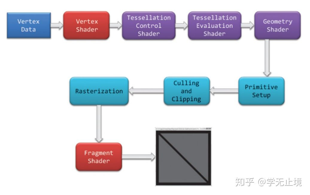
- GPU渲染的是一个一个的三角形
- 一个面只要顶点够多,就能生成一个平滑的曲面
– 在低端机可以让三角形【顶点】少一些 - 动态生成一个mesh,是一个平面,并且三角形足够的多
- 通过一张外部图片【噪声】的信息,来存储云的凹凸信息
– 一张图只有黑白灰,越白的地方,让三角形的高度越高,反之亦然 - 让这张贴图运动【滚动】起来,随着时间的变化,修改获取uv的位置信息
– 这样三角形就可以变化了 - 通过读取多张噪声,或者读取同一张噪声不同位置的地方,叠加起来,就可以获得翻涌的感觉了
3. 行动
多说无益,实践才是最好的
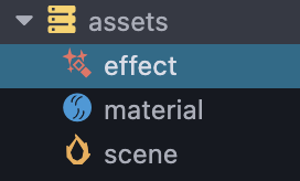
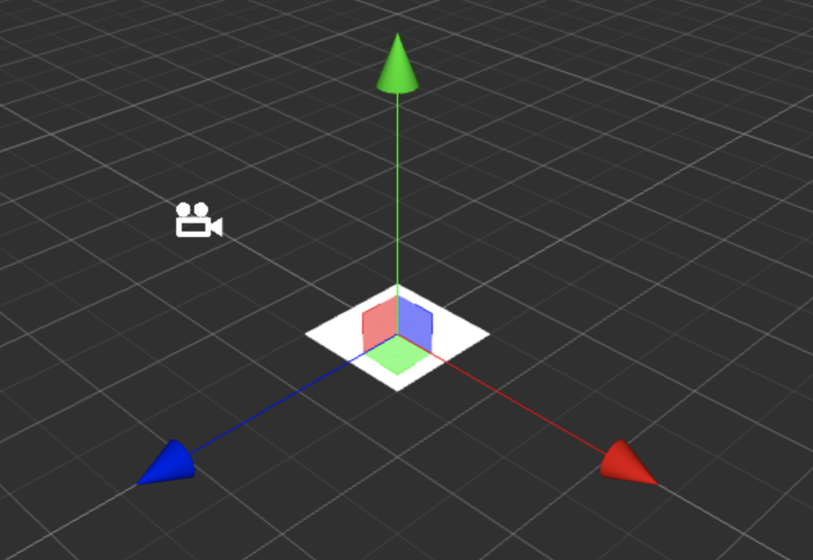
3.1 首先创建默认的场景,材质,和effect文件
3.2 编辑effect文件
双击打开effect, 获得了默认的cocos的shader文件
// Effect Syntax Guide: https://github.com/cocos-creator/docs-3d/blob/master/zh/material-system/effect-syntax.md

CCEffect %{
  techniques:
  - name: opaque
    passes:
    - vert: general-vs:vert # builtin header
      frag: unlit-fs:frag
      properties: &props
        mainTexture:    { value: white }
        mainColor:      { value: [1, 1, 1, 1], editor: { type: color } }
  - name: transparent
    passes:
    - vert: general-vs:vert # builtin header
      frag: unlit-fs:frag
      blendState:
        targets:
        - blend: true
          blendSrc: src_alpha
          blendDst: one_minus_src_alpha
          blendSrcAlpha: src_alpha
          blendDstAlpha: one_minus_src_alpha
      properties: *props
}%

CCProgram unlit-fs %{
  precision highp float;
  #include <output>
  #include <cc-fog-fs>

  in vec2 v_uv;
  uniform sampler2D mainTexture;

  uniform Constant {
    vec4 mainColor;
  };

  vec4 frag () {
    vec4 col = mainColor * texture(mainTexture, v_uv);
    CC_APPLY_FOG(col);
    return CCFragOutput(col);
  }
}%
可以看到一行
- vert: general-vs:vert # builtin header
根据后面的注释,可以知道,这里使用了默认的builtin的顶点着色器
参考cocos官方文档:
Effect Syntax · Cocos Creator
所以这个文件里面缺少了要编写的顶点着色器,所以要手动补充一个
找到自带的chunks里面的general-vs
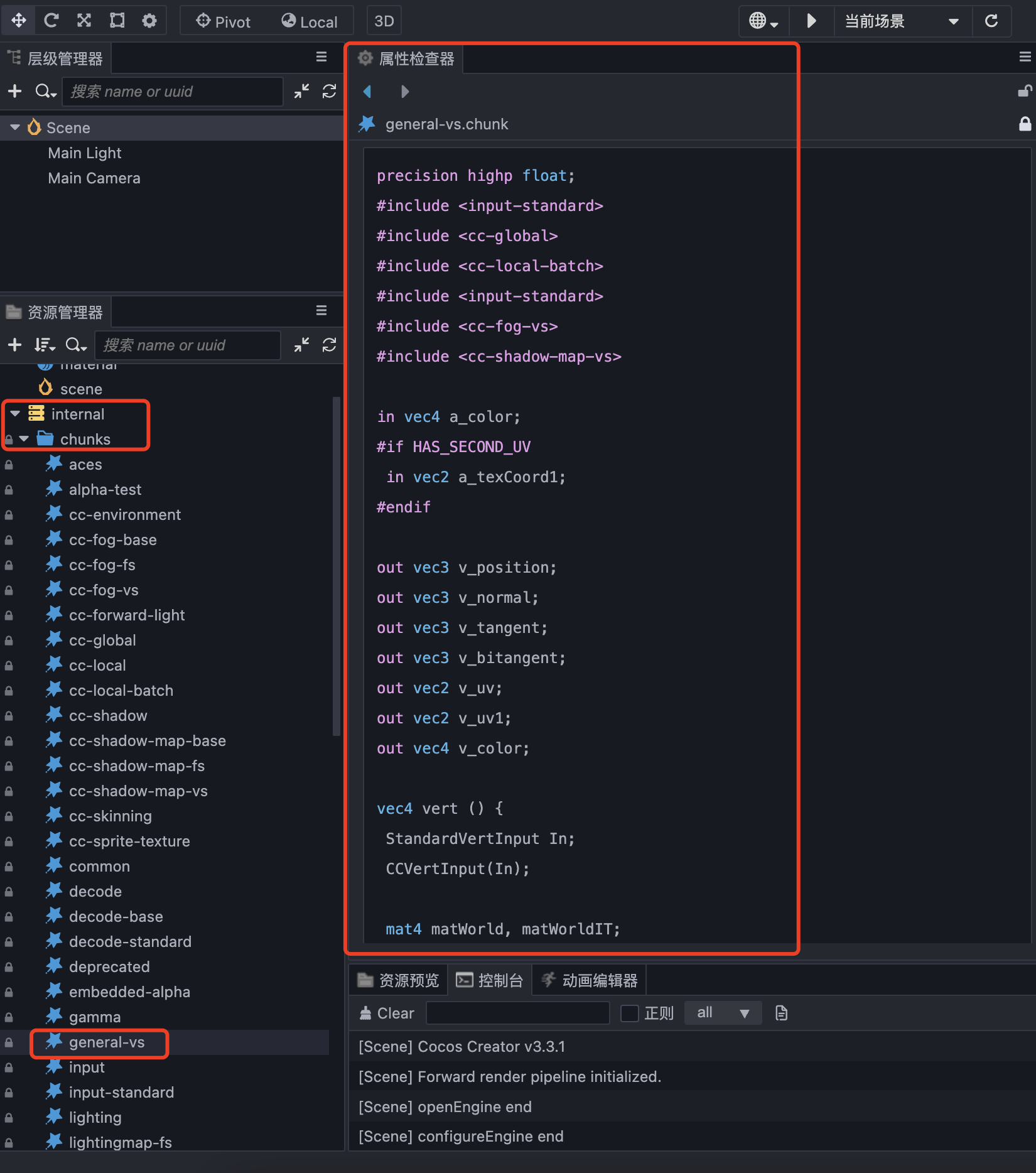
将内容复制出来
回到effect文件中,补充一个
CCProgram块my-vs
CCProgram my-vs %{

  precision highp float;
  #include <input-standard>
  #include <cc-global>
  #include <cc-local-batch>
  #include <input-standard>
  #include <cc-fog-vs>
  #include <cc-shadow-map-vs>

  in vec4 a_color;
  #if HAS_SECOND_UV
    in vec2 a_texCoord1;
  #endif

  out vec3 v_position;
  out vec3 v_normal;
  out vec3 v_tangent;
  out vec3 v_bitangent;
  out vec2 v_uv;
  out vec2 v_uv1;
  out vec4 v_color;

  vec4 vert () {
    StandardVertInput In;
    CCVertInput(In);

    mat4 matWorld, matWorldIT;
    CCGetWorldMatrixFull(matWorld, matWorldIT);

    vec4 pos = matWorld * In.position;

    v_position = pos.xyz;
    v_normal = normalize((matWorldIT * vec4(In.normal, 0.0)).xyz);
    v_tangent = normalize((matWorld * vec4(In.tangent.xyz, 0.0)).xyz);
    v_bitangent = cross(v_normal, v_tangent) * In.tangent.w; // note the cross order

    v_uv = a_texCoord;
    #if HAS_SECOND_UV
      v_uv1 = a_texCoord1;
    #endif
    v_color = a_color;

    CC_TRANSFER_FOG(pos);
    CC_TRANSFER_SHADOW(pos);

    return cc_matProj * (cc_matView * matWorld) * In.position;
  }

}%
并且将最上面的CCEffect的vert部分定义修改成
CCEffect %{
  techniques:
  - name: opaque
    passes:
    - vert: my-vs:vert # builtin header
      frag: unlit-fs:frag
      properties: &props
        mainTexture:    { value: white }
        mainColor:      { value: [1, 1, 1, 1], editor: { type: color } }
  - name: transparent
    passes:
    - vert: general-vs:vert # builtin header
      frag: unlit-fs:frag
      blendState:
        targets:
        - blend: true
          blendSrc: src_alpha
          blendDst: one_minus_src_alpha
          blendSrcAlpha: src_alpha
          blendDstAlpha: one_minus_src_alpha
      properties: *props
}%
3.3 绑定effect到材质上
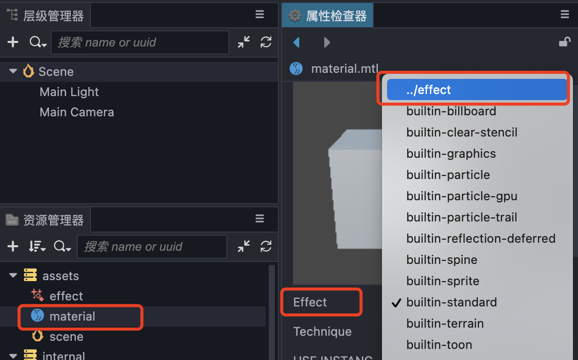
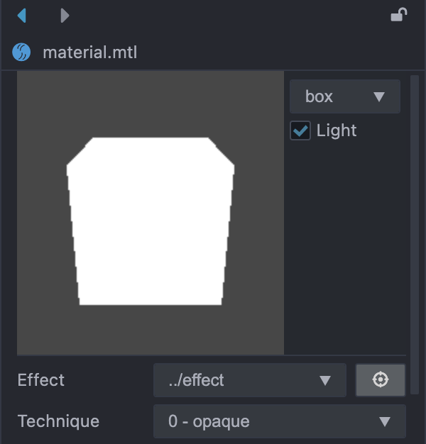
选中材质,选择Effect,选中刚刚新建的effect文件,最后不要忘记点击右上角的箭头,保存一下
正确的话会预览出一个纯白的方块
3.4 创建plane,并应用材质
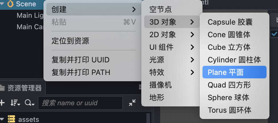
场景中创建3D对象,Plane
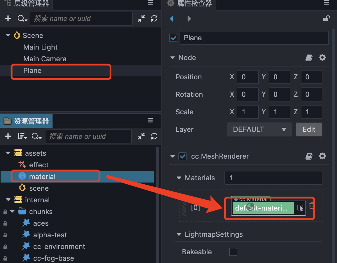
选中Plane节点,将material拖拽覆盖原本的default-material材质
最终可以得到一个纯白的Plane
3.5 准备噪声贴图
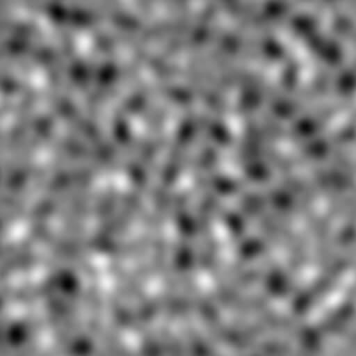
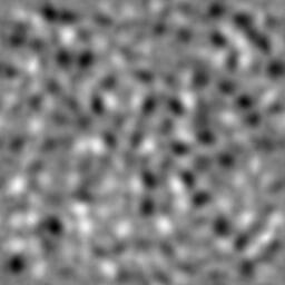
这里有两张噪声,简单看上去,他们好像并没有区别,但是如果让UV偏移0.5的话就会发生奇怪的问题
先简单修改下片元着色器,也就是frag块
CCProgram unlit-fs %{
  precision highp float;
  #include <output>
  #include <cc-fog-fs>

  in vec2 v_uv;
  uniform sampler2D mainTexture;

  uniform Constant {
    vec4 mainColor;
  };

  vec4 frag () {
    vec4 col = mainColor * texture(mainTexture, v_uv + 0.5);
    CC_APPLY_FOG(col);
    return CCFragOutput(col);
  }
}%
3.5.1 修改了UV的取值
这里将v_uv增加了0.5
3.5.2 回到cocos creator编辑器,将两张噪声分别放进材质里,看看会发生什么
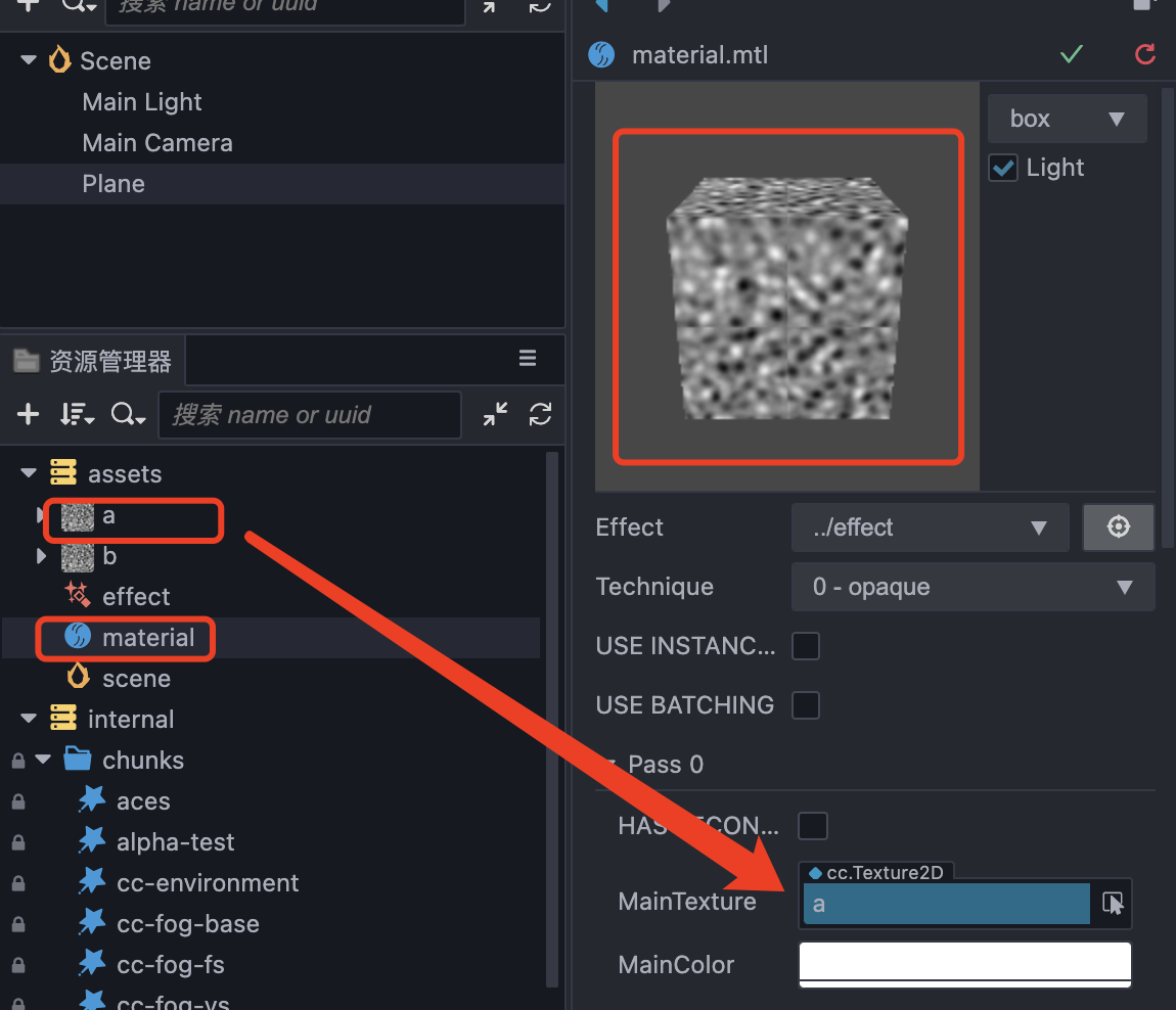
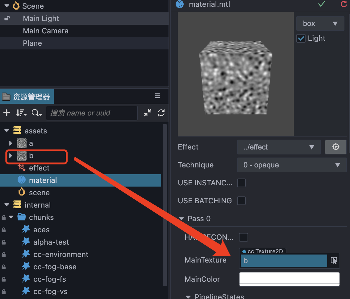
可以很明显的发现噪声在偏移之后,中间并不平滑
所以这里使用的噪声贴图有一个条件:无缝噪声
测试完记得吧+0.5删掉
测试完记得吧+0.5删掉
测试完记得吧+0.5删掉
3.6 修改顶点着色器,让顶点位置发生变化
  uniform sampler2D mainTexture;

  vec4 vert () {
    StandardVertInput In;
    CCVertInput(In);

    mat4 matWorld, matWorldIT;
    CCGetWorldMatrixFull(matWorld, matWorldIT);

    vec4 p = In.position;

    float y = texture(mainTexture, a_texCoord).x;
    p.y = y;


    vec4 pos = matWorld * p;

    v_position = pos.xyz;
    v_normal = normalize((matWorldIT * vec4(In.normal, 0.0)).xyz);
    v_tangent = normalize((matWorld * vec4(In.tangent.xyz, 0.0)).xyz);
    v_bitangent = cross(v_normal, v_tangent) * In.tangent.w; // note the cross order

    v_uv = a_texCoord;
    #if HAS_SECOND_UV
      v_uv1 = a_texCoord1;
    #endif
    v_color = a_color;

    CC_TRANSFER_FOG(pos);
    CC_TRANSFER_SHADOW(pos);

    return cc_matProj * (cc_matView * matWorld) * p;
  }
3.6.1 定义mainTexture
uniform sampler2D mainTexture;
3.6.2 定义p = In.position; 并且用p代替后续代码中的In.position
3.6.3 读取mainTexture中对应UV位置的颜色,由于是黑白灰的噪声,所以r==g==b,直接将r的颜色赋值给p.y
3.6.4 后续不要忘记使用p来代替In.position来计算
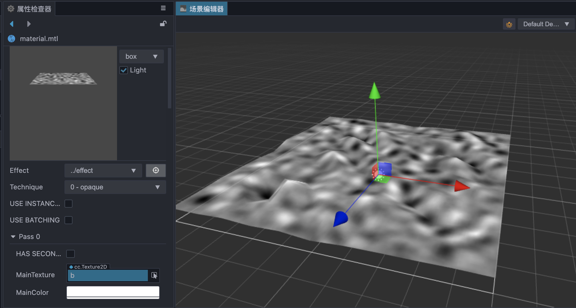
回到cocos creator就可以发现Plane变的凹凸不平,并且越黑的地方越低,越白的地方越高
3.7 平滑
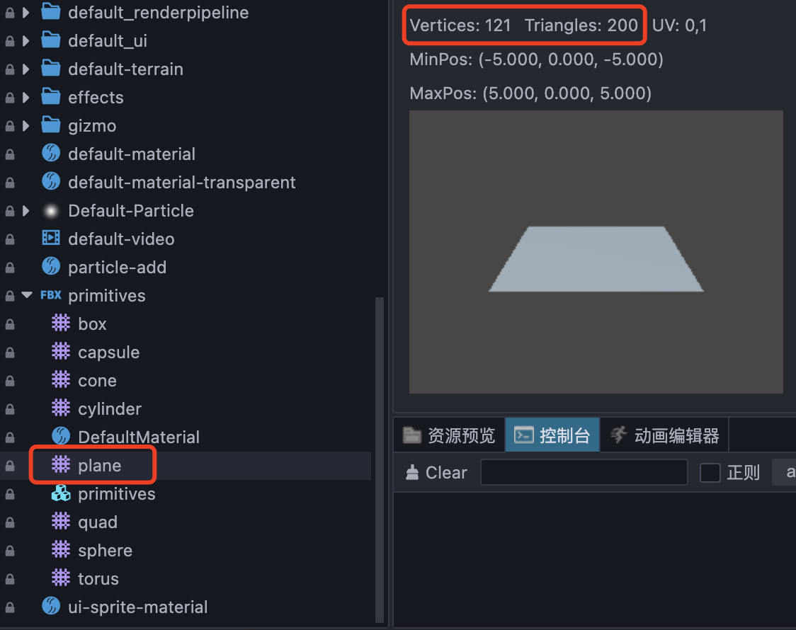
默认的Plane面数比较少,所以会变的比较不平滑
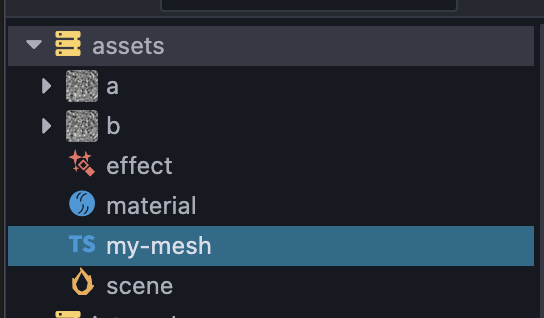
创建一个脚本,叫my-mesh,用来替换plane的默认mesh
import { _decorator, Component, utils, primitives, MeshRenderer } from 'cc';

const { ccclass, property } = _decorator;


@ccclass('MyMesh')
export class MyMesh extends Component {
    start () {
        const renderer = this.node.getComponent(MeshRenderer);
        if(!renderer){
            return;
        }
        const plane: primitives.IGeometry = primitives.plane({
            width: 10,
            length: 10
            widthSegments: 100,
            lengthSegments: 100,
        });

        renderer.mesh = utils.createMesh(plane);
    }

}
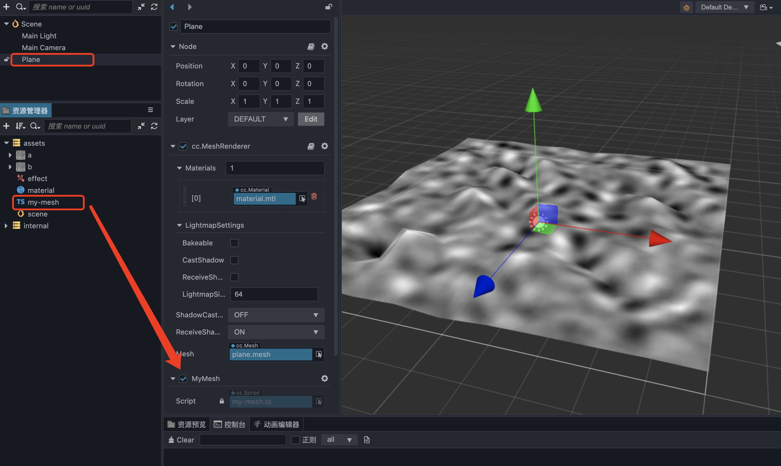
回到Cocos,将脚本和Node绑定起来,并且运行
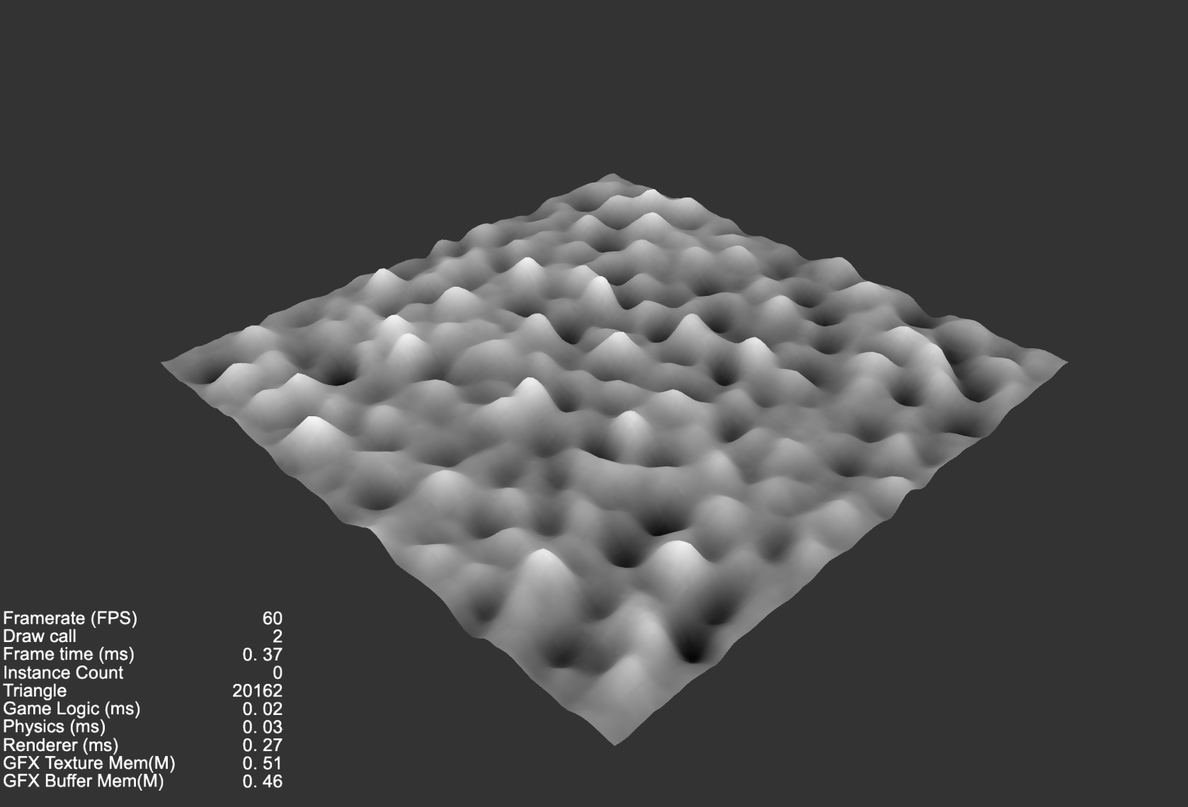
可以看到,相对编辑器中的已经平滑了许多,并且很容易的区分出高低的颜色
3.8 运动
引入时间戳(单位:s),根据时间的不同, 获取不同位置的uv信息,就可以让画面滚动起来
#incloud
  uniform sampler2D mainTexture;

  #include <cc-global>
  vec4 vert () {
    StandardVertInput In;
    CCVertInput(In);

    mat4 matWorld, matWorldIT;
    CCGetWorldMatrixFull(matWorld, matWorldIT);

    vec4 p = In.position;

    float y = texture(mainTexture, a_texCoord + cc_time.x * 0.1).x;
    p.y = y;


    vec4 pos = matWorld * p;

    v_position = pos.xyz;
    v_normal = normalize((matWorldIT * vec4(In.normal, 0.0)).xyz);
    v_tangent = normalize((matWorld * vec4(In.tangent.xyz, 0.0)).xyz);
    v_bitangent = cross(v_normal, v_tangent) * In.tangent.w; // note the cross order

    v_uv = a_texCoord;
    #if HAS_SECOND_UV
      v_uv1 = a_texCoord1;
    #endif
    v_color = a_color;

    CC_TRANSFER_FOG(pos);
    CC_TRANSFER_SHADOW(pos);

    return cc_matProj * (cc_matView * matWorld) * p;
  }

}%
3.8.1 引入 #incloud cc-global
3.8.2 修改 uv的获取,a_texCoord 值加上cc_time.x并且*一个速度系数0.1
3.9 颜色
形状是发生改变了,但是颜色好像并没有重新发生变化
3.9.1 修改顶点着色器,将texture函数获取到的颜色,直接丢给v_color
3.9.2 修改片元着色器,直接将v_color颜色返回【记得先声明 in vec4 v_color;】
CCProgram my-vs %{

  precision highp float;
  #include <input-standard>
  #include <cc-global>
  #include <cc-local-batch>
  #include <input-standard>
  #include <cc-fog-vs>
  #include <cc-shadow-map-vs>

  in vec4 a_color;
  #if HAS_SECOND_UV
    in vec2 a_texCoord1;
  #endif

  out vec3 v_position;
  out vec3 v_normal;
  out vec3 v_tangent;
  out vec3 v_bitangent;
  out vec2 v_uv;
  out vec2 v_uv1;
  out vec4 v_color;

  uniform sampler2D mainTexture;

  #include <cc-global>
  vec4 vert () {
    StandardVertInput In;
    CCVertInput(In);

    mat4 matWorld, matWorldIT;
    CCGetWorldMatrixFull(matWorld, matWorldIT);

    vec4 p = In.position;

    vec4 baseColor0 = texture(mainTexture, a_texCoord + cc_time.x * 0.1);
    p.y = baseColor0.x;


    vec4 pos = matWorld * p;

    v_position = pos.xyz;
    v_normal = normalize((matWorldIT * vec4(In.normal, 0.0)).xyz);
    v_tangent = normalize((matWorld * vec4(In.tangent.xyz, 0.0)).xyz);
    v_bitangent = cross(v_normal, v_tangent) * In.tangent.w; // note the cross order

    v_uv = a_texCoord;
    #if HAS_SECOND_UV
      v_uv1 = a_texCoord1;
    #endif
    v_color = baseColor0;

    CC_TRANSFER_FOG(pos);
    CC_TRANSFER_SHADOW(pos);

    return cc_matProj * (cc_matView * matWorld) * p;
  }

}%

CCProgram unlit-fs %{
  precision highp float;
  #include <output>
  #include <cc-fog-fs>

  in vec2 v_uv;
  in vec4 v_color;
  uniform sampler2D mainTexture;

  uniform Constant {
    vec4 mainColor;
  };

  vec4 frag () {
    return v_color;
  }
}%
可以发现没有刚刚的问题了,回到越白的地方越高,越黑的地方越暗了
3.10 噪声叠加【翻涌】
噪声可以用多张,也可以读取多次,只要读取的位置不一样,并且叠加起来,那么就可以得到翻涌的感觉了
说上来可以比较抽象,实际行动下
  vec4 vert () {
    StandardVertInput In;
    CCVertInput(In);

    mat4 matWorld, matWorldIT;
    CCGetWorldMatrixFull(matWorld, matWorldIT);

    vec4 p = In.position;

    vec4 tiling0 = vec4(1.0, 1.0, 0.1, 0.1);
    vec4 tiling1 = vec4(1.0, 1.0, 0.07, 0.07);
    vec4 baseColor0 = texture(mainTexture, a_texCoord * tiling0.xy + cc_time.x * tiling0.zw);
    vec4 baseColor1 = texture(mainTexture, a_texCoord * tiling1.xy + cc_time.x * tiling1.zw);
    p.y = (baseColor0.x + baseColor1.x) * 0.5 - 0.5;


    vec4 pos = matWorld * p;

    v_position = pos.xyz;
    v_normal = normalize((matWorldIT * vec4(In.normal, 0.0)).xyz);
    v_tangent = normalize((matWorld * vec4(In.tangent.xyz, 0.0)).xyz);
    v_bitangent = cross(v_normal, v_tangent) * In.tangent.w; // note the cross order

    v_uv = a_texCoord;
    #if HAS_SECOND_UV
      v_uv1 = a_texCoord1;
    #endif
    v_color = (baseColor0 + baseColor1)* 0.5;

    CC_TRANSFER_FOG(pos);
    CC_TRANSFER_SHADOW(pos);

    return cc_matProj * (cc_matView * matWorld) * p;
  }
3.10.1 定义了tiling0和tiling1,其中,xy用来控制uv的倍率,zw用来控制uv移动的方向
3.10.2 texture采样两次,分别为baseColor0何baseColor1,并且两个颜色的红色加起来*0.5,赋值给p.y
3.10.3 p.y最后还- 0.5,是因为y的值原本在0~1之间,希望最后在-0.5~0.5之间分布,所以整体-0.5
3.10.4 将v_color = baseColor0改成v_color = (baseColor0 + baseColor1)* 0.5;
可以发现运动不再和上面一样单一运动,而是带上起伏的感觉
3.11 颜色过渡
黑白灰毕竟不好看,所以希望自定义两个颜色来重新定义高低
    vec4 c0 = vec4(1.0, 0.0, 0.0, 1.0);
    vec4 c1 = vec4(0.0, 1.0, 0.0, 1.0);

    v_color = (p.y + 0.5) * (c0 - c1) + c1;
定义两个颜色c0和c1,用来表示最高处和最低处的两个地方的颜色
c0表示最高处的颜色
c1表示最低处的颜色
c0 - c1= 两个颜色的差距
p.y + 0.5得到一个0~1之间的值,用来表示当前y的高度
(p.y + 0.5) * (c0 - c1)得到一个y高度变化中的过渡值
过渡值+c1,表示过渡值+基础值=最终的颜色
c0 - c1等于两个颜色分量的差,用差*(y + 0.5)得到变化值,最后在加上c1
这样就得到了一个自定义颜色的shader
3.12 将定义的数据暴露给材质面板
目前位置,这里定义了两个tiling,两个颜色c0和c1
CCEffect %{
  techniques:
  - name: opaque
    passes:
    - vert: my-vs:vert # builtin header
      frag: unlit-fs:frag
      properties: &props
        mainTexture:    { value: white }
        mainColor:      { value: [1, 1, 1, 1], editor: { type: color } }
        c0:      { value: [1, 0, 0, 1], editor: { type: color } }
        c1:      { value: [0, 1, 0, 1], editor: { type: color } }
        tiling0:   { value: [1.0, 1.0, 0.1, 0.1] }
        tiling1:   { value: [1.0, 1.0, 0.07, 0.07] }
  - name: transparent
    passes:
    - vert: general-vs:vert # builtin header
      frag: unlit-fs:frag
      blendState:
        targets:
        - blend: true
          blendSrc: src_alpha
          blendDst: one_minus_src_alpha
          blendSrcAlpha: src_alpha
          blendDstAlpha: one_minus_src_alpha
      properties: *props
}%
将c0, c1, tiling0, tiling1定义到properties里面,原来的参数这里先不做任何删改,保留处理
给顶点着色器和片元着色器都加上uniform声明定义块
  uniform MyVec4 {
    vec4 c0;
    vec4 c1;
    vec4 tiling0;
    vec4 tiling1;
  };
然后移除原本代码里面定义的c0, c1, tiling0和tiling1,用uniform来代替
最终完整的effect文件内容为:
// Effect Syntax Guide: https://github.com/cocos-creator/docs-3d/blob/master/zh/material-system/effect-syntax.md

CCEffect %{
  techniques:
  - name: opaque
    passes:
    - vert: my-vs:vert # builtin header
      frag: unlit-fs:frag
      properties: &props
        mainTexture:    { value: white }
        mainColor:      { value: [1, 1, 1, 1], editor: { type: color } }
        c0:      { value: [1, 0, 0, 1], editor: { type: color } }
        c1:      { value: [0, 1, 0, 1], editor: { type: color } }
        tiling0:   { value: [1.0, 1.0, 0.1, 0.1] }
        tiling1:   { value: [1.0, 1.0, 0.07, 0.07] }
  - name: transparent
    passes:
    - vert: general-vs:vert # builtin header
      frag: unlit-fs:frag
      blendState:
        targets:
        - blend: true
          blendSrc: src_alpha
          blendDst: one_minus_src_alpha
          blendSrcAlpha: src_alpha
          blendDstAlpha: one_minus_src_alpha
      properties: *props
}%

CCProgram my-vs %{

  precision highp float;
  #include <input-standard>
  #include <cc-global>
  #include <cc-local-batch>
  #include <input-standard>
  #include <cc-fog-vs>
  #include <cc-shadow-map-vs>

  in vec4 a_color;
  #if HAS_SECOND_UV
    in vec2 a_texCoord1;
  #endif

  out vec3 v_position;
  out vec3 v_normal;
  out vec3 v_tangent;
  out vec3 v_bitangent;
  out vec2 v_uv;
  out vec2 v_uv1;
  out vec4 v_color;

  uniform sampler2D mainTexture;

  uniform MyVec4 {
    vec4 c0;
    vec4 c1;
    vec4 tiling0;
    vec4 tiling1;
  };

  #include <cc-global>
  vec4 vert () {
    StandardVertInput In;
    CCVertInput(In);

    mat4 matWorld, matWorldIT;
    CCGetWorldMatrixFull(matWorld, matWorldIT);

    vec4 p = In.position;

    vec4 baseColor0 = texture(mainTexture, a_texCoord * tiling0.xy + cc_time.x * tiling0.zw);
    vec4 baseColor1 = texture(mainTexture, a_texCoord * tiling1.xy + cc_time.x * tiling1.zw);
    p.y = (baseColor0.x + baseColor1.x) * 0.5 - 0.5;


    vec4 pos = matWorld * p;

    v_position = pos.xyz;
    v_normal = normalize((matWorldIT * vec4(In.normal, 0.0)).xyz);
    v_tangent = normalize((matWorld * vec4(In.tangent.xyz, 0.0)).xyz);
    v_bitangent = cross(v_normal, v_tangent) * In.tangent.w; // note the cross order

    v_uv = a_texCoord;
    #if HAS_SECOND_UV
      v_uv1 = a_texCoord1;
    #endif

    v_color = (p.y + 0.5) * (c0 - c1) + c1;

    CC_TRANSFER_FOG(pos);
    CC_TRANSFER_SHADOW(pos);

    return cc_matProj * (cc_matView * matWorld) * p;
  }

}%

CCProgram unlit-fs %{
  precision highp float;
  #include <output>
  #include <cc-fog-fs>

  in vec2 v_uv;
  in vec4 v_color;
  uniform sampler2D mainTexture;

  uniform Constant {
    vec4 mainColor;
  };

  uniform MyVec4 {
    vec4 c0;
    vec4 c1;
    vec4 tiling0;
    vec4 tiling1;
  };

  vec4 frag () {
    return v_color;
  }
}%
回到cocos中,查看材质
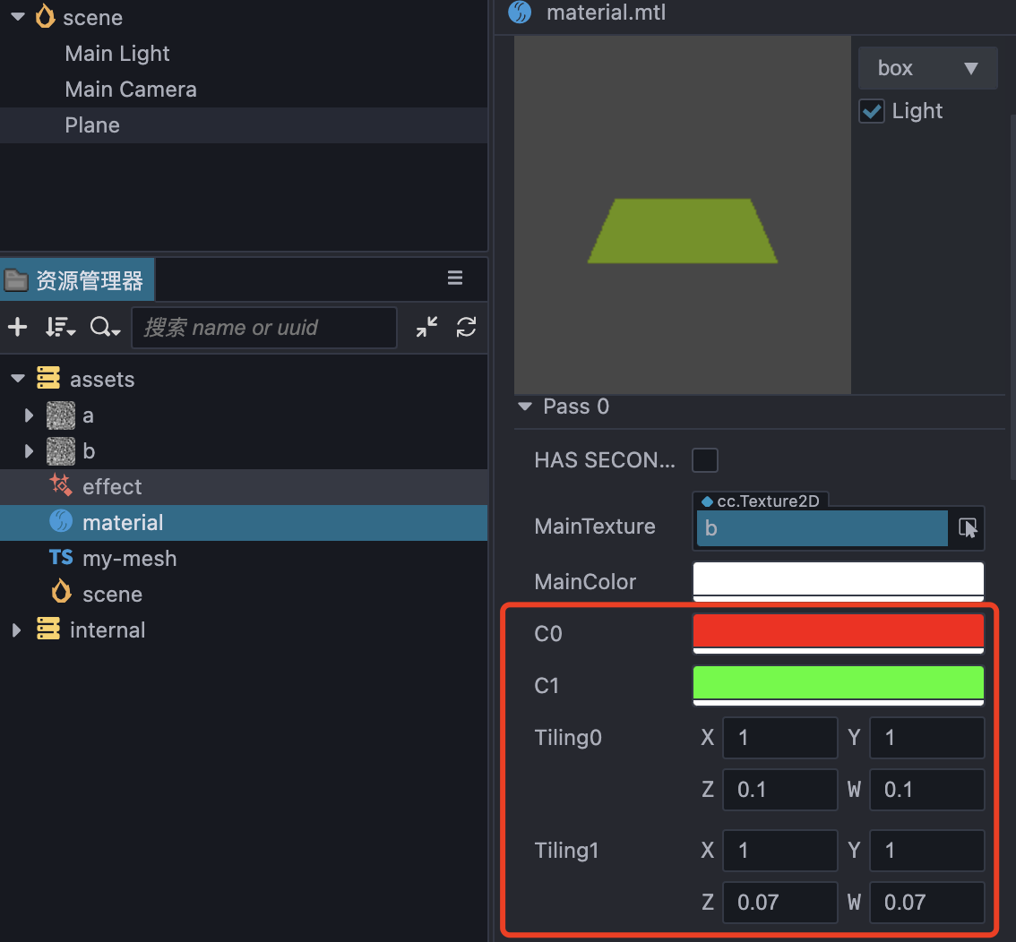
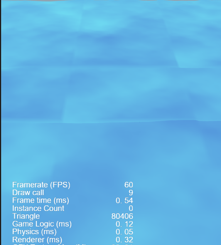
4. 成果
调整一下摄像机,材质的参数
4.1 最小可预览工程
版本:CocosCreator 3.3.1
learn.zip (45.8 KB)
Other 软件渲染器
https://github.com/Jecced/raster


